
Raman amplifier is appearing to be a critical technology which is consistently developed for using in optical communication networks. Typically applied in long-haul networks, Raman amplifier is also expected to extend its reach in dense wavelength-division multiplexing (DWDM) networks. This escalating adoption, therefore, is fueled by the massive bandwidth demand that network operators are continuously facing. This article explains the necessities and related considerations for deploying Raman amplifier in DWDM networks.
Raman amplifier has proved itself beneficial for applications in 100G network and above. It is gaining in popularity because it is capable of meeting the need for higher transmission capacity. There exist various alternatives to enhance network transmission capacity: like extending beyond the C-band into the L-band, increasing the symbol rate or increasing spectral efficiency. Any of the options require a higher optical signal-to-noise ratio (OSNR). Raman amplifier generally offers higher OSDR required to increase capacity, while eliminates the need for expensive opto-electronic regeneration.

Raman amplification generally leverages the network fiber as the gain medium. By adding a distribution Raman amplifier to a fiber span with EDFAs, signal power loss can be decreased. The commonly deployed counter-propagating Raman amplifier consists of one or more Raman pump lasers and a wavelength combiner, so that the Raman pump wavelengths are transmitted into the fiber in the opposite direction of the signal. Signal propagating along the fiber will be attenuated, but as it moves along toward the fiber end where the Raman pump is located, it will start to experience some gain from the Raman pump wavelength. The higher power in the signal thus increases OSDR, which enables longer fiber span, higher capacity and spectral efficiency, and longer link distance.
With EDFA being the default amplifier for use in DWDM transmission, Raman amplifier is found critical and effective in complementing the EDFA for transmission distance expansion. It typically provides an improvement in performance that cannot be obtained by EDFA alone. The application of Raman amplifier in DWDM network is demonstrated below.
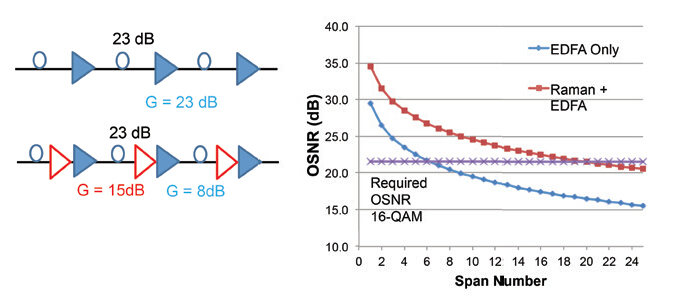
The following picture illustrates the effect of Raman amplification on a simple multispan link with 23 dB loss per span compensated by 23 dB of amplification. In one case, each span loss is compensated with an EDFA, while in the other case, the gain is divided between the distributed Raman amplifier and the EDFA. Inferring from the figure, it is clearly that with the hybrid EDFA/Raman amplification, the OSNR curve has shifted upwards towards higher OSNR values. This means the link can obtain higher OSNR for the same span number, or, the same OSNR for a much larger span number. By incorporating Raman amplifier into DWDM networks, the link becomes more robust, with more margin available for future repairs or changes along the link.
It is undoubted that Raman amplifier can provide significant benefit to DWDM networks, what should be noticed here is that, there are also several key precautions to deploy Raman amplifier in real-life environment, which must be addressed so that the potential benefits can be fully realized.
When deploying Raman amplifier in a DWDM system, the equipment needs to be connected to the network fiber with minimum connection loss. Since contamination like dust and dirt, or misalignment is detrimental to fiber attenuation, network operators must keep the fiber and connectors clean during the connection process, not degrade the performance of the system.
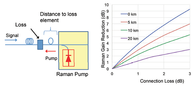
Connection loss could have a significant impact on the whole network. The following picture shows the reduction in Raman gain due to different connector losses when the connector is located very close to the Raman pump. The three curves correspond to different fiber attenuation levels at 1550 nm. In this example, a Raman amplifier with a net gain of 15 dB is involved, a 1 dB connection loss can result in a 4 dB gain reduction, and a 2dB connection loss increases the reduction in Raman gain to 7 dB.

The location of the loss element serves as a vital factor. The figure below shows the Raman gain reduction according to different position of the loss elements, at 0 km, 5 km, 10 km and 20 km away from the Raman pump. It reveals that the Raman gain reduction is lower if the connection loss is located further away from the Raman pump. This is because most of the Raman gain occurs close to the Raman pump. We can also conclude that most of the gain obtained through Raman amplification is obtained in the region of the effective length of the fiber, which is in the ~20km range.
Adoption of Raman amplifier significantly consolidates optical link while extends transmission reach in DWDM networks. Raman amplifier also serves as a good implementation of EDFAs, enabling applications which are not feasible or practical with conventional EDFA technology. Thus increasing the distance and capacity of long-haul DWDM systems.


