Power-over-Ethernet is technology formalized under the Institute of Electrical and Electronic (IEEE) standard. By combining power and communications over a single UTP cable like Cat 3 or Cat 5 cable, engineers can construct low-maintenance Ethernet networks quickly and inexpensively compared with installations employing separate system, the key advantages of PoE technology are its simplicity and the fact that power is available wherever there is a data socket.
Development of PoE
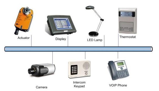
PoE is first introduced as a solution to power Voice over Internet Protocol (VoIP) phones. Traditional phones took their power directly from the copper wire carrying voice calls. However, the Increasing popular VoIP phones were not connected to these conventional circuit, instead taking calls over the Ethernet cables of a company’s Local Area Network (LAN). As the Ethernet cable can not carry power, so the VoIP phones had to be plugged in to the mains supply via an adapter. It was a less-than-elegant solution, and if the building power was lost, the phone will stop working.
In 2000, telecommunication equipment vendor Cisco firstly mimic the traditional phone system by introducing proprietary technology that allowed Ethernet cables to carry a 48 VDC supply to power VoIP phones. PoE really gained momentum in 2001 and 2002, as other manufacturers, particularly Wireless Access Point makers, took advantage of the technique.
In 1983, the IEEE organization, thought it is necessary to create a standard version of PoE so that any manufacturer could make their products workable with PoE. The work was assigned to a working subcommittee of the IEEE 802.3 Ethernet Committee and named “802.3af”. By June, 2003 the working subcommittee ratified the IEEE 802.3af PoE Standard. In 2009, a second standard, IEEE 802.3at, was ratified which defined a similar technology that could handle more power.
IEEE PoE Standard
PoE technology is used as single, standard RJ45 connector and Cat 5 cable, and can handle tens of watts. Once the Ethernet network is installed for communication, it can also be served as power, saving on materials, labor, installation time, and ongoing maintenance costs.
Power may be transmitted on the used conductors of the Ethernet cable, since only two of the four pairs of Cat 5 cabling is required for the typical 10 to 100 Mbps physical layer. Power also may be transmitted on the data conductors of the cable by applying a common-mode voltage to each pair. As Ethernet uses differential signaling, this does not interfere with the cable’s data
transmission.
802.3af Possible Devices
IEEE 802.3af defines two types of PoE devices, Power Sourcing Equipment (PSE) and the Powered Device (PD). A PSE draws power from its own conventional power supply and then manages the power sent over the Ethernet cable network to the PD, which takes the power it needs via a RJ45 connector without a building-in power supply. PoE provides a flexible and convenient means of powering devices that are located in out-of-the-way locations, and saved costs by eliminating the expense and difficulty of direct electrical wiring. A challenge with PoE is reaching remote locations outside the distance limitation of UTP cabling. The maximum length for a cable segment is 100 meters, while PoE power injectors or midspans do not increase the distance of the data link.
PoE Media Converters
Fiber optics is the best solutions to get beyond the 100-meter limit. Fiber optic cabling is an effective method to overcome the distance and bandwidth limitation of UTP. To integrate copper network equipment with fiber optic, the PoE media converter is needed, which is a good solution to extend network distance via fiber to remote PD devices such as the original VoIP phones and wireless Access Points, security cameras, Point-of-sale (POS) terminals, temperature control systems, and even in-flight entertainment systems. A PoE media converter converts the fiber to copper, and sends DC power to the PDs over the UTP cabling.
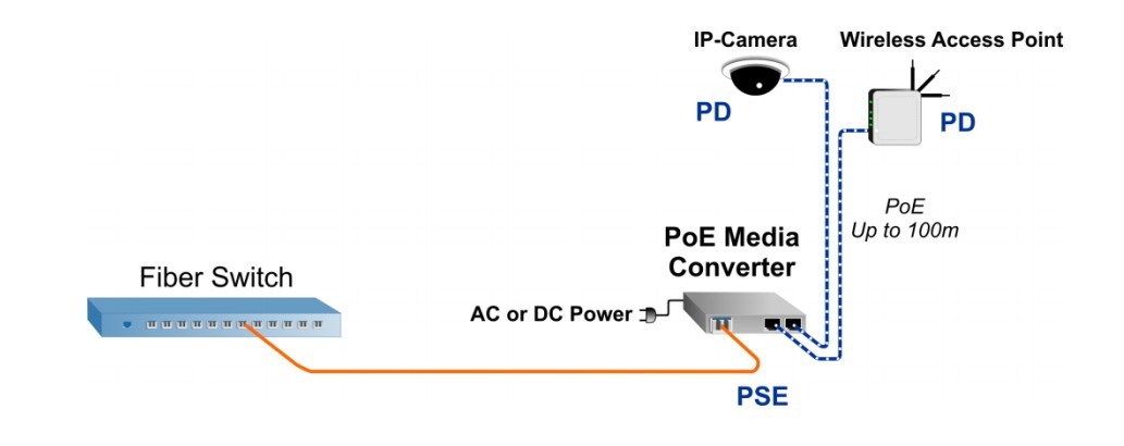
Picture show How PoE media converter works
With a standard PoE media converter, the copper UTP cabling is converted to fiber. The fiber is run for a long distance to the PoE media converter located near a convenient AC or DC power source, where
it converts the fiber back to copper UTP. The PoE media converter also functions as a power-sourcing mini switch, and injects PoE (DC power) over the UTP cable. At the other end of the UTP cable is the PD devices like a IP Cameras, located up to 100 meters away from the PoE media converter.
PoE media converter are available with 10/100/1000Base-T(X) to 1000Base-FX Gigabit Ethernet and 10/100Base-T(X) to 100Base-FX Fast Ethernet PoE Converter Fast Ethernet data rates and can support PoE (15.4 watts) or PoE+ (25.5 watts). The PoE media converters function like PoE switch, and are available in a variety of multi-port configurations including dual RJ-45 and dual fiber ports. They can support fixed fiber connectors or small form pluggable (SFP) transceivers.
Multi-port PoE media converters make the network design flexible. They typically feature single or dual RJ-45 ports to power one or two PDs like IP cameras per converter, and single or dual fiber ports.
Single fiber PoE media converters are deployed in a point-to-point, network start topology. In this network, the PDs e.g. IP cameras are installed throughout a facility fiber. Fiber is distributed from a fiber switch, a copper switch or media converters. The fiber links connect to distant locations where PoE media converters are installed near AC or DC power sources. The PoE media converters convert the fiber to copper and inject PoE over the UTP cabling to the IP cameras.
PoE media converters with dual fiber ports enable linking multiple media converters in a line daisy chain configuration. This architecture can be used in a variety of outdoor applications where PDs such as IP cameras and/or wireless access points are installed along railroad and subway lines, highways, pipelines, mine shafts, perimeter fences, etc.
Dual fiber ports also link multiple media converters in a ring architecture. The fiber switch shown in this diagram supports spanning tree to enable a redundant ring architecture. In the event of a fiber failure in the ring, the fiber switch would reroute the traffic in the opposite direction.
Dual fiber ports can be used to deploy redundant fiber links for mission-critical applications requiring fiber facility protection. There is an active fiber port, and a protection fiber port, that can support a fiber failure switchover of less than 50 milliseconds.
PoE media converters combine the benefits of PoE or PoE+ and fiber optic cabling in a compact, reliable and cost-effective device. Classified as Power Sourcing Equipment (PSE), the PoE media converters provide power to Powered Devices (PDs) using the same UTP cables that carry the Ethernet data. This enables powering devices in hard-to-reach locations where there is limited access to AC power outlets, or locations where AC power creates safety issues.
FiberStore is one of the main suppliers of PoE media converters on the market to support the high-power PoE+ standard. Models are available in Gigabit 1000BASE-X fiber to 10/100/1000 UTP and Fast Ethernet 100BASE-FX fiber to 10/100 UTP.
A variety of port configurations are available, including single or dual SFP and single or dual powered UTP ports. Models with dual SFP ports support critical applications that require redundancy and sub 50ms switch over in the event of a fiber failure. The product is DC powered and available with an optional external 100 – 240VAC universal power adapter.
For ordering 10/100M Dual Fiber PoE Media Converter, please check below chart. If you want more information on our PoE media converters, please visit www.fs.com.


