When a connector is installed on the fiber end, loss will be incurred. Some light loss would be reflected back directly down the fiber towards the light source that generated it. These back reflections, or Optical Return Loss (ORL) will damage the laser light sources and also disrupt the transmitted signal. Fiber connectors with different polishing types have different back reflections (see the picture below). With the development of technology, four polishing types are available: flat-surface, Physical Contact (PC), Ultra Physical Contact (UPC), and Angled Physical Contact (APC). How one evolves into another? This article will tell the answer.
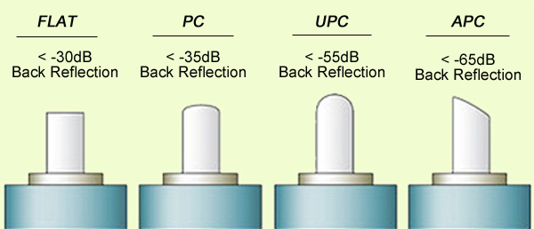
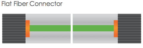
The original fiber connector is a flat-surface connection, or a flat fiber connector. The primary issue of it is that a small air gap between the two ferrules is naturally left when mated. This is partly because the relatively large end-face of the connector allows for numerous slight but significant imperfections to gather on the surface. The flat fiber connector is not suitable for single-mode fiber cables with a 9µm core size, thus it is essential to evolve into Physical Contact (PC) connectors.
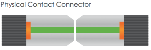
The Physical Contact is polished with a slight spherical design to reduce the overall size of the end-face, which helps to decrease the air gap issue faced by Flat Fiber connectors. It results in lower Optical Return Loss (ORL) with less light being sent back towards the power source.
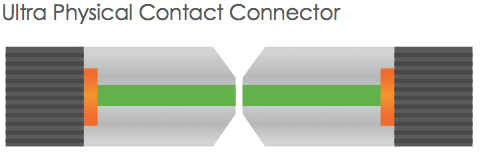
Building on the convex end-face attributes of the PC, but utilizing an extended polishing method creates an even finer fiber surface finish: Ultra Physical Contact (UPC) connector. It has a lower back reflection (ORL) than a standard PC connector and allows more reliable signals in digital TV, telephony and data systems. UPC fiber connector could be used with both single-mode fiber and multimode fiber. Usually the UPC single-mode fiber connector is blue, but the UPC multimode fiber connector is beige. (Note: 10G UPC multimode fiber connector is aqua.)
PC and UPC connectors do have a low insertion loss, but the back reflection (ORL) depends on the the surface finish of the fiber. The finer the fiber grain structure, the lower the back reflection. When PC and UPC connectors are continually mated and unmated, the back reflection will begin to degrade. So there is a need for a connector with low back reflection and it could sustain repeated matings/unmatings without ORL degradation.
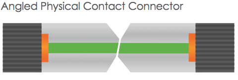
The end faces of Angled Physical Contact connectors are still curved but are angled at an industry standard eight degrees, which allows for even tighter connections and smaller end-face radii. Combined with that, any light that is redirected back towards the source is actually reflected out into the fiber cladding, again by the virtue of the 8°angled end-face. APC connector back reflection does not degrade with repeated matings/unmatings. APC fiber connector can only be used with single-mode fiber and it is green.
It is clear that all of the connector end-face options mentioned above take a place in the market. And it is hard to claim that one connector beats the others when your specification needs to consider cost and simplicity not just optical performance. Your particular need decides which one to choose. For those applications calling for high precision optical fiber signaling, APC should be the first consideration, but less sensitive digital systems will perform equally well using UPC. For various connector options, please visit FS.COM.
Article source: www.fiber-optic-components.com/evolution-of-flat-pc-upc-and-apc-fiber-connectors.html

