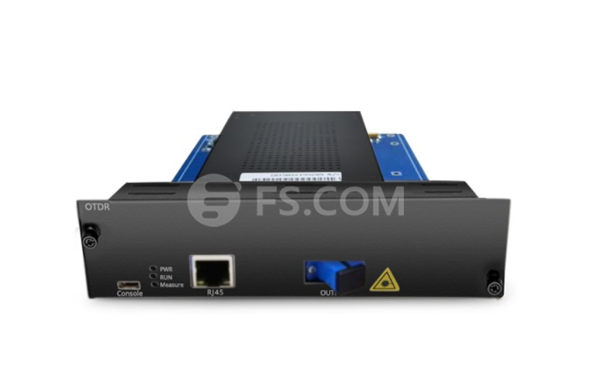
OTDR, the full name is Optical Time Domain Reflectometer. It is a precise optoelectronic integrated fiber optic test equipment. OTDR tester is widely used for optical cable maintenance and construction. This article will focus on the OTDR working principle and OTDR characteristics.
OTDR Working Principle
OTDR working principle, we need to start from the process of OTDR testing. During the process of OTDR testing, the equipment injects a higher power laser or fiber optic light source pulse into a fiber from one end of the fiber cable. And then it receives the return information at the OTDR port. When the optical pulse is transmitted through the fiber, there will be a scattered reflection. Because of the nature of the fiber, the connector, the engagement points, bending, etc. Part of the scattering and reflection will return to the OTDR. Useful information returned will be measured by the OTDR detector. And it acts as the time or curve segments of fibers at different positions. By recording the transmission time of the signals, we can get the transmission speed of the light in the glass fibers and the distance.
OTDR testing has some limitation when it comes to measuring the outside cable plant loss. The OTDR tester will not be always useful for testing. Because it doesn’t work well with short cables in a building or LAN environment. Because the source and power meter used for the tasks are not equipped to show actual cable plant loss.
OTDR Characteristics
To test fibers’ characteristics, OTDR uses Rayleigh scatting and Fresnel reflection. Rayleigh scattering is an irregular scattering. It is generated when the optical signals transmitting in the fiber. OTDR only test the scattered light back on the OTDR port. The backscatter signal shows the attenuation degree (loss/distance) of the optical fiber. And it will be tracked as a downward curve. It illustrates the decreasing power of backscatter. This is because of both the transmission signal and backscatter loss are attenuated.
Rayleigh scattering power can be marked with optical parameters. If the wavelength is known, it is ratable with the pulse width of the signal. The longer is the pulse width, the stronger is the backscatter power. Rayleigh scattering power is also related to the wavelength of the transmitted signal. The shorter is the wavelength, the stronger is the power. That is to say, the backscatter loose generated by the trajectory of 1310nm will be higher than that of 1550nm signals.
In the higher wavelength region (more than 1500nm), the Rayleigh scattering will continue to decrease. And the other one phenomenon which called infrared attenuation (or absorption) will appear to increase. Then it causes an increase of the overall attenuation values. Therefore, the 1550nm wavelength is the lowest attenuation. This also shows why it is a long distance communication wavelength. Naturally, these phenomena will return to affect the OTDR. OTDR of 1550nm wavelength also has low attenuation. So it can be used for long distance testing. While at the high attenuation wavelength of 1310nm or 1625nm, OTDR testing distance is bound to be limited. Because the test equipment needs to test a sharp front in the OTDR trace. And the end of the spikes will quickly fall into the noise area.
Fresnel reflection is a discrete reflection. It is caused by the individual point of the whole fibers. These points are caused by a change in reverse coefficient elements such as glass and the air gap. At these points, there will be a strong backscattering light reflected back. Thus, by using the information of Fresnel reflection, OTDR locate the connection point, fiber optic terminal or breakpoints.
Conclusion
OTDR working principle and OTDR characteristics are extensively introduced in this article. An OTDR tester is essentially an optical radar. It sends out a flash of bright light and measures the intensity of echo or reflections. So this weak signal is averaged to reduce detection noise. Besides computation is used to display a trace and make a number of mathematical deductions.
Related Article: General Guide to OTDR
Basics of OTDR (Optical Time-Domain Reflectometer)