
SFP+ transceiver is widely deployed in applications and becomes much more pervasive due to its smaller form factor, less power consumption and its increased port density compared with XFP transceiver. Each SFP+ transceiver houses an optical receiver and transmitter. One end of the transceiver is an optical connection complying with the 10GbE and 8GFC standards, while the other end is an SERDES framer interface (SFI) serial interconnect handling differential signals up to 10 Gbit/s. In order to keep a SFP+ transceiver achieving high performance, the engineers need to acquaint with the key challenges related to testing SFP+ transceiver. This article will first walk through the SFP+ transceiver test challenges and then focus on one kind of SFP+ transceiver test measurement.
SFP+ Transceiver Test Challenges
- One obvious challenge is the increased port density and the testing time required with 48 or more ports per rack.
- Another challenge is moving seamlessly from a compliance environment to a debug environment.
- Yet another problem most designers face today relates to connectivity: how to get the signal out from the device under test (DUT) to an oscilloscope.
- Another challenge to prepare for is that the SFP+ specification calls out some measurements to be performed using a PRBS31 signal.
- Additionally, acquiring a record length of 200 million data points demands huge processing power and time.
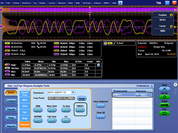
SFP+ Transceiver Test: TWDPc Measurement
TWDPc, short for transmitter waveform distortion penalty for copper, requires a special algorithm defined by the SFP+ specification. This test is defined as a measure of the deterministic dispersion penalty due to a particular transmitter with reference to the emulated multimode fiber and a well-characterized receiver.
The TWDPc script (of 802.3aq, 10GBASE-LRM) processes a PRBS9 pattern requiring at least 16 samples per unit interval. Out of concern for the large installed base of equivalent-time oscilloscopes with a record length of around 4000 samples, the requirement for 16 samples per unit interval was relaxed to seven samples per unit interval.
The relaxation of the requirement from 16 samples per unit interval to just seven samples per unit interval causes worst-case pessimism of 0.24 dB TWDPc over 30 measurements. For DUTs that already have a high TWDPc, 0.24 dB can be the difference between a pass or a fail result.
The TWDPc measurement for SFP+ host transmitter output specifications for copper requires more than 70 Gsamples/s to capture a minimum of seven samples per UI. Real-time oscilloscopes offering higher sampling rates of 100 Gsamples/s or greater have a much higher chance of providing accurate results for TWDPc compared to scopes that only offer lower sampling-rate options.
Across the board, it is important to map the SFP+ signal’s data-transfer rate to the proper oscilloscope bandwidth requirements to ensure accuracy in measurement and margin testing. With a 10.3125-Gbyte/s data-transfer rate and minimum rise time of 34 ps, a scope with a bandwidth of 16 GHz or higher is required to meet the minimum requirements for SFP+. As noted, sampling rate is also an important consideration for the TWDPc measurement.
Conclusion
Although SFP+ transceiver simplifies the functionality of the 10G optical module, it introduces some test and measurement challenges. TWDPc is a key test for SFP+ transceiver test. It defines the differences (in dB) between a reference signal and noise ratio (SNR) and the equivalent SNR at the slicer input of a reference equalizer receiver for the measurement waveform after propagating through a stimulus channel. For SFP+ compliance testing, TWDPc is a required measurement.