
WDM technology is commonly used in today’s optical networks. It basically assigns each service (10G LAN, SONET/SDH, Fiber Channel, etc) an independent dedicated wavelength—which then is multiplexed into one single fiber. Eliminating the use of multiple fibers while increasing fiber capacity, the WDM system is beneficial to both service providers and end-users. Optical transponder, also referred to as O-E-O (optical-electrical-optical), serves as an integrated part of the WDM system and it is critical for signal transmission in the whole system. This article will guide you through how optical transponder operates in a WDM network.
The optical WDM transponder (O-E-O) works as a re-generator which converts an optical input signal into electrical form, then generates a logical copy of an input signal and uses this signal to drive a transmitter to generate an optical signal at the new wavelength (optical-electrical-optical). Its most prominent feature is that it automatically receives, amplifies, and then re-transmits a signal on a different wavelength without altering the data/signal content. Clients can be electrical or optical (1310 or 1550 nm), co-located or some distance away. Line side interfaces can be fiber, CWDM or DWDM with a variety of reaches supported.

The optical transponder is widely accepted in WDM networking and many other applications. let’s go through some commonly used ones.
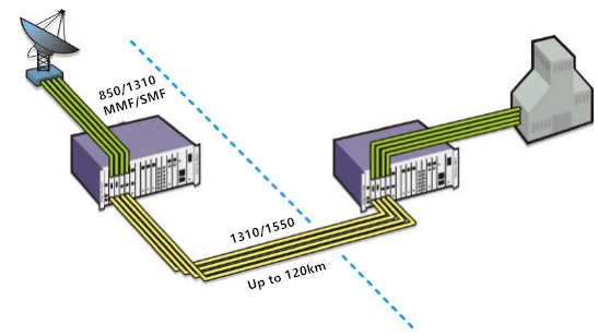
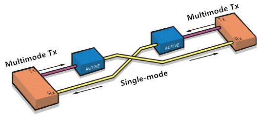
Some optical transponders can convert from multimode to single-mode fiber, short reach to long reach lasers, and/or 850/1310 nm to 1550 nm wavelengths. Each optical transponder module is protocol transparent and operates fully independent of the adjacent channels.
Each optical transponder module can also include a redundant fiber path option for extra protection. The redundant fiber option transmits the source signal over two different optical paths to two redundant receivers at the other end. If the primary path is lost, the backup receiver is switched on. Since this is done electronically, it is much faster and more reliable.

As an optical repeater, some optical transponders effectively extend an optical signal to cover the desired distance. With the clock recovery option, a degraded signal can be debittered and retransmitted to optimize signal quality.
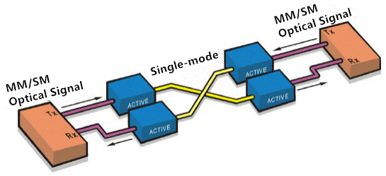
Mode conversion is one of the quickest and simplest ways of extending multimode optical signals over greater distances on signal-mode fiber optics. And most receivers are capable of receiving both multimode and single-mode optical signals.
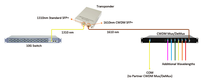
Wavelength conversion in commercial networks today is only carried out by optical transponder. We know that optical network equipment with conventional fiber interfaces like LC, SC, ST, etc operates over legacy wavelengths of 850 nm, 1310 nm, and 1550 nm. This means they must be converted to CWDM or DWDM wavelength to fit in the system, and this is what WDM transponders used for—converse wavelength by automatically receiving, amplifying, and re-transmitting a signal on a different wavelength without altering the data/signal content. The following picture depicts the conversion process: a 10G switch (with signal output of 1310 nm) is to be linked to a CWDM Mux/Demux channel port (1610 nm). An optical transponder with a standard SMF SFP+ and a 1610nm CWDM SFP+ is adopted between the switch and CWDM Mux/Demux, thus the wavelength conversion is realized by the optical transponder.
Then how exactly optical transponder benefits your network system? Here we provide two possible configurations of network over WDM ring which deploys optical transponder.
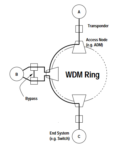
The line network consists basically of two point-to-point links between A-B and B-C, each requiring transponders at the endpoints. If node B fails, communication between A and C should still be possible, because B can be bypassed by the two adjacent optical transponders. For this the protection in/outputs of the transponders are connected by a bypass link. If node B fails, S1 in both transponders switch to the protection connection.
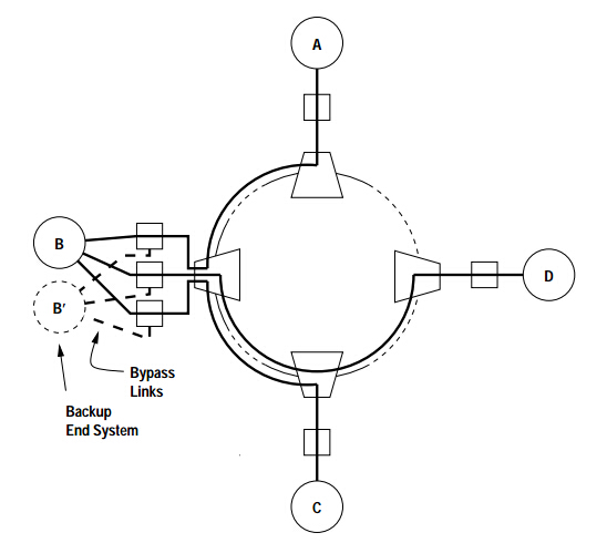
As for a star network over a WDM ring, where the nodes A, C and D are connected to the star node B. Node B has a backup node B’ for redundancy. Here the protection in/outputs of the transponders are used to connect the nodes A, C and D to node B’ if node B failed.
Optical transponder holds a critical position in the WDM networking system and cannot simply be underestimated. We have illustrated the functionality and applications of optical transponder, as well as presenting possible configurations of the network over WDM rings. Hope that may help you to have a better understanding of the optical transponder.